Version:2025/02/25
Table of Contents:
Objective:
Confirm the operation of I2C, GPIO, and SPI supported by Marmot (SPI is excluded in this demo).
Processing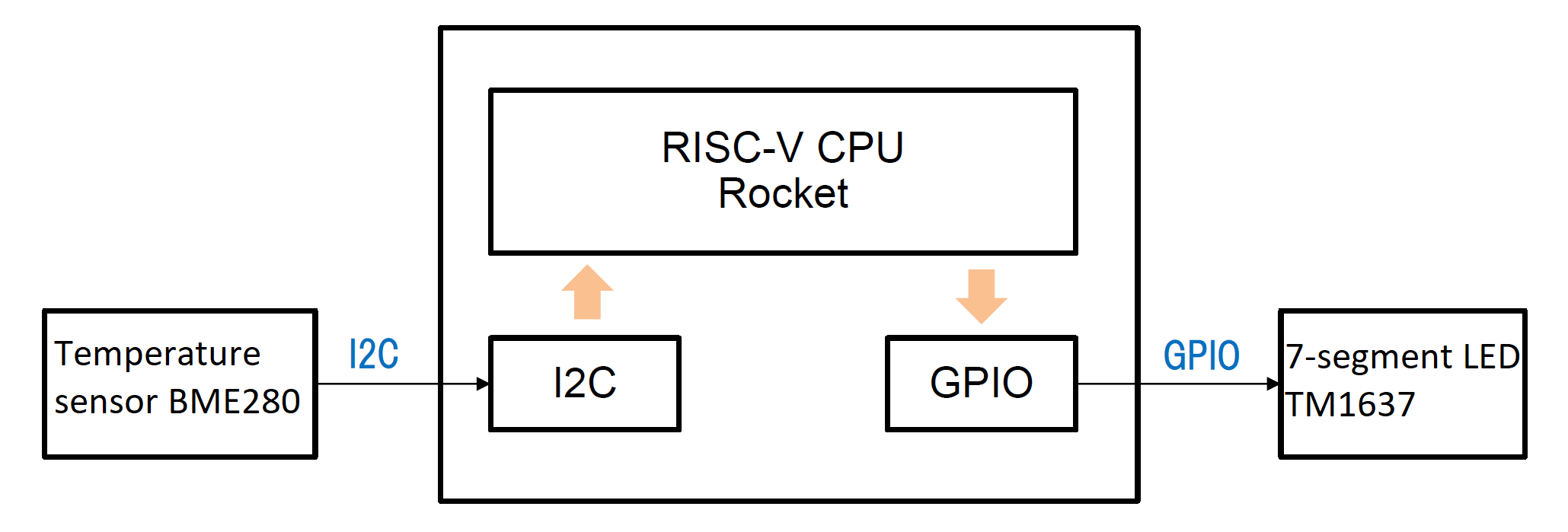
I2C0_REG(OC_I2C_PRER_LO) = 0x0f;
I2C0_REG(OC_I2C_PRER_HI) = 0x0;

I2C0_REG(OC_I2C_CTR) = OC_I2C_EN;
Pink lines: Prescaler settings
Yellow lines: Enabling 2C
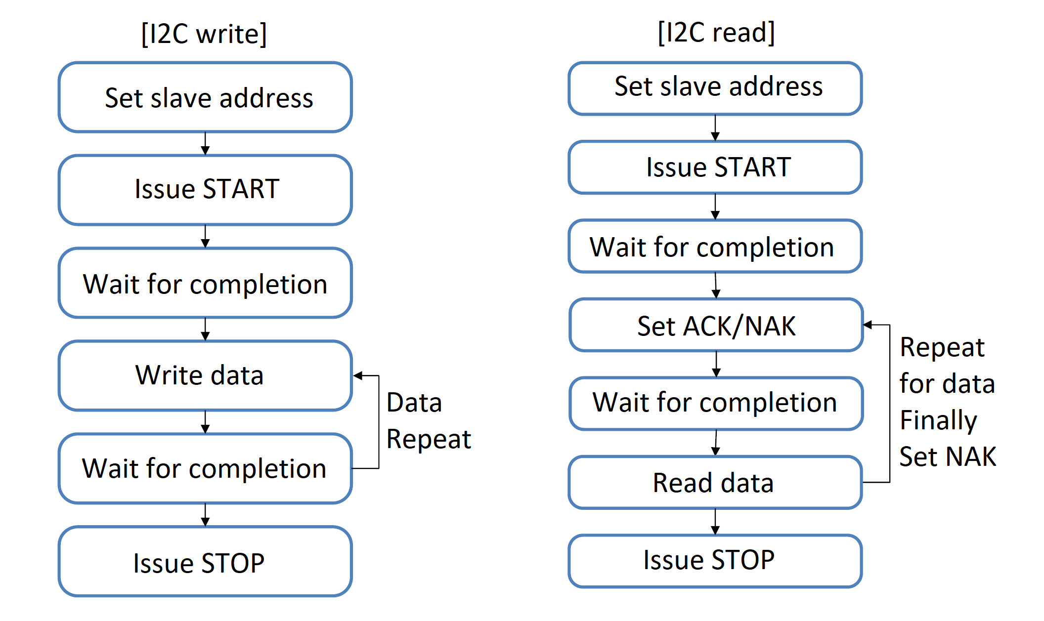
Marmot's I2C write/read functions.
| Documents | Location |
|---|---|
| Documentation | https://www.bosch-sensortec.com/products/environmental-sensors/humidity-sensors-bme280 |
| Sample Code | https://github.com/boschsensortec/BME280_SensorAPI |
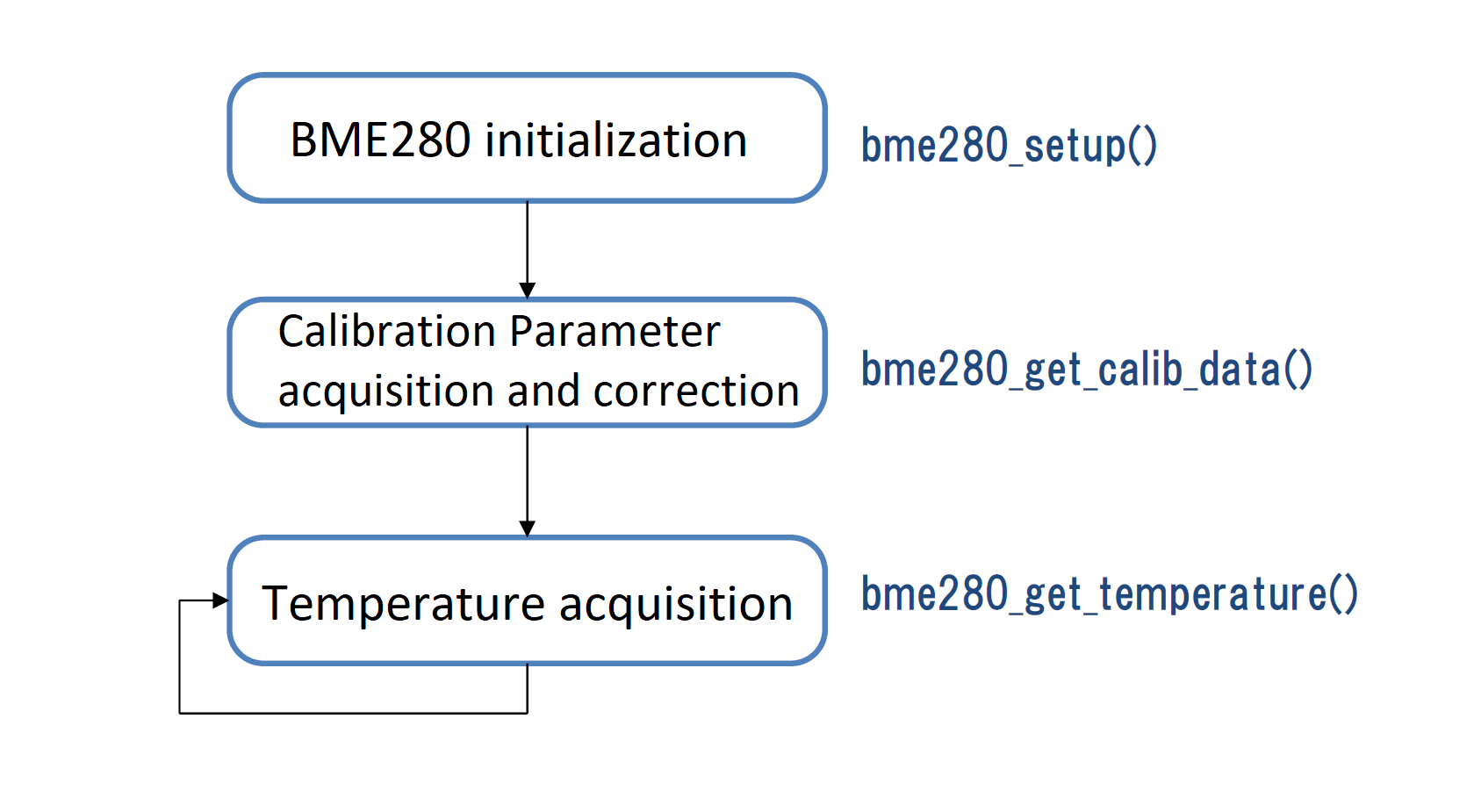
Control flow for BME280.
The GPIO specifications are found in the Freedom FE310 Manual
Chapter 10, Figure 10.
Documents: English versions are available below
https://github.com/revolunet/tm1637/blob/master/datasheet-en.pdf
Features:=> Open-drain control similar to I2C is assumed?
Controls like the gpio-i2c driver in Linux:Set interfaces for OE control and output data on GPIO.
  reg_mprj_io_13 = GPIO_MODE_USER_STD_BIDIRECTIONAL; // IO3
  reg_mprj_io_12 = GPIO_MODE_USER_STD_BIDIRECTIONAL; // IO2
  reg_mprj_io_11 = GPIO_MODE_USER_STD_BIDIRECTIONAL; // IO1
  reg_mprj_io_10 = GPIO_MODE_USER_STD_BIDIRECTIONAL; // IO0
SPI Flash Instruction Format Register (ffmt)
| Bits | Field Name | Attr. | Rst. | Description |
|---|---|---|---|---|
| 0 | cmd_en | RW | 0x1 | Enable sending of command |
| [3:1] | addr_len | RW | 0x3 | Number of address bytes (0 to 4) |
| [7:4] | pad_cnt | RW | 0x0 | Number of dummy cycles |
| [9:8] | cmd_proto | RW | 0x0 | Protocol for transmitting command |
| [11:10] | addr_proto | RW | 0x0 | Protocol for transmitting address and padding |
| [13:12] | data_proto | RW | 0x0 | Protocol for receiving data bytes |
| [15:14] | Reserved | |||
| [23:16] | cmd_code | RW | 0x3 | Value of command byte |
| [31:24] | pad_code | RW | 0x0 | First 8 bits to transmit during dummy cycles |
For example, below code set the SPI Flash Instruction Format Register to use Fast Read in QPI mode:
  // Set XIP access to Quad mode
  dummy =   SPI_INSN_CMD_EN
          | SPI_INSN_ADDR_LEN(0x3)
          | SPI_INSN_PAD_CNT(0x2)
          | SPI_INSN_CMD_PROTO(SPI_PROTO_Q)
          | SPI_INSN_ADDR_PROTO(SPI_PROTO_Q)
          | SPI_INSN_DATA_PROTO(SPI_PROTO_Q)
          | SPI_INSN_CMD_CODE(0x0b)   // Fast read
          | SPI_INSN_PAD_CODE(0x00);

  while (_REG32(spi_base_addr, SPI_REG_RFMT) != dummy) {
    _REG32(spi_base_addr, SPI_REG_RFMT) = dummy;
  }
  // Set SPI Flash to Quad mode
  while (_REG32(spi_base_addr, SPI_REG_TXFIFO) & SPI_TXFIFO_FULL);  // Wait until TX FIFO not full
    _REG32(spi_base_addr, SPI_REG_TXFIFO) = CMD_ENTER_QUAD_MODE;  // 0x38
Note: This function needs to be executed on ITIM (Instruction Tightly Integrated Memory) instead of QSPI Flash.
__attribute__ ((section (".text_itim"))) void init_spi(uint32_t spi_base_addr)
{
  volatile uint32_t dummy;

  asm volatile ("fence\n\t"
                "fence.i");

  // Set SPI clock
  while (_REG32(spi_base_addr, SPI_REG_SCKDIV) != SCKDIV) {
    _REG32(spi_base_addr, SPI_REG_SCKDIV) = SCKDIV;
  }

  // Disable XIP mode
  while (_REG32(spi_base_addr, SPI_REG_RCTRL) != 0x0) {
    _REG32(spi_base_addr, SPI_REG_RCTRL) = 0x0;
  }

  // Set SPI Flash to Quad mode
  while (_REG32(spi_base_addr, SPI_REG_TXFIFO) & SPI_TXFIFO_FULL);  // Wait until TX FIFO not full
  _REG32(spi_base_addr, SPI_REG_TXFIFO) = CMD_ENTER_QUAD_MODE;

  // Set XIP access to Quad mode
  dummy =   SPI_INSN_CMD_EN
          | SPI_INSN_ADDR_LEN(0x3)
          | SPI_INSN_PAD_CNT(0x2)
          | SPI_INSN_CMD_PROTO(SPI_PROTO_Q)
          | SPI_INSN_ADDR_PROTO(SPI_PROTO_Q)
          | SPI_INSN_DATA_PROTO(SPI_PROTO_Q)
          | SPI_INSN_CMD_CODE(0x0b)   // Fast read
          | SPI_INSN_PAD_CODE(0x00);

  while (_REG32(spi_base_addr, SPI_REG_RFMT) != dummy) {
    _REG32(spi_base_addr, SPI_REG_RFMT) = dummy;
  }

  // Enable XIP mode
  while (_REG32(spi_base_addr, SPI_REG_RCTRL) != SPI_FCTRL_EN) {
    _REG32(spi_base_addr, SPI_REG_RCTRL) = SPI_FCTRL_EN;
  }
}
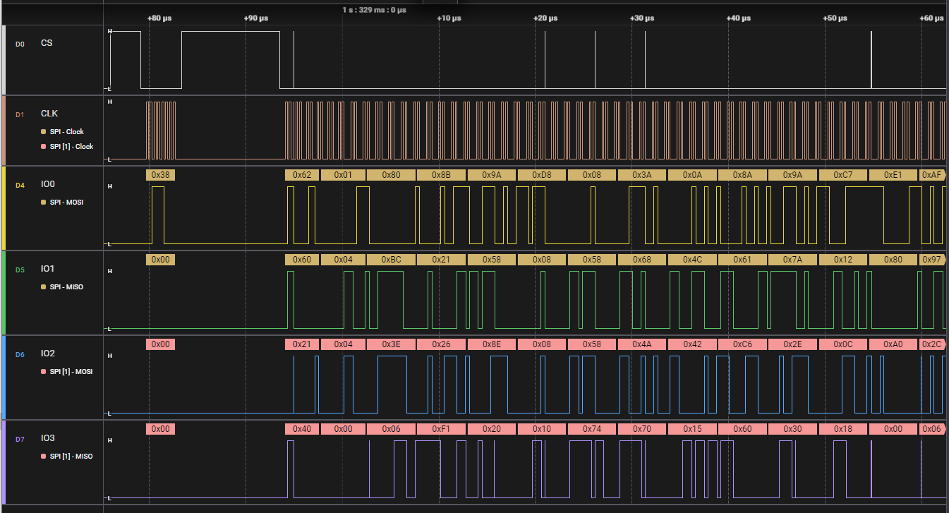
Below is the result that run the QSPI flash in QPI mode:
Copyright © Japan Embedded Systems Technology Association All Rights Reserved.